Several years ago I published this post about making DIY sit-&-stand computer station. Do I still use it? Yes, I do. And I am constantly modifying it. Since the beginning of COVID pandemic I work remotely and unlikely will ever return back to the office. If two years ago I spent in my home office several hours per week now I am spending there ~ 50 hours. Here is how my office looks now:
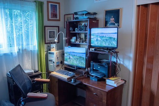
My nine years old computer (CPU Intel Xeon E2-1230 V2) is still OK. Mostly I use it to run Remote Desktop application to get access to my job machines, but it is sufficient to run browsers, compile small and medium sized hobby projects and do some photo or video editing . I upgraded it several times: now it has 32 GB of RAM, its main disk is 1 TB SSD (plus couple of TB in regular hard drives), and it has NVIDA GeForce GT1030 2 GB video card. Obviously spec is not impressive but good enough. As my main movable display I use Philips 252B with 1920x1200 resolution ( higher resolution creates too much strain on my eyes). As peripheral display there is Lenovo LI2323swA with 1920x1080 resolution.). Lenovo monitor in this set up is not movable and it is OK to accommodate on its screen applications with which are am not working at the moment.
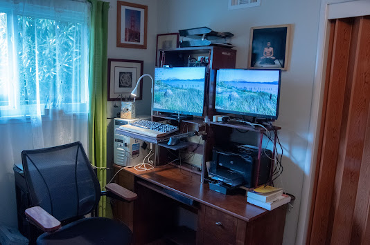
Here is how it looks when Philips is in UP position.
Honestly speaking most of the time I work sitting, so it is important to have comfortable chair. When work became exclusively remote we allowed to take home some furniture from the office, so I took chair. It is comfortable and convenient and serves me well.
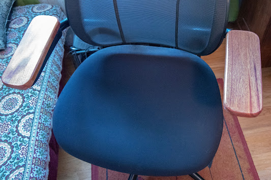
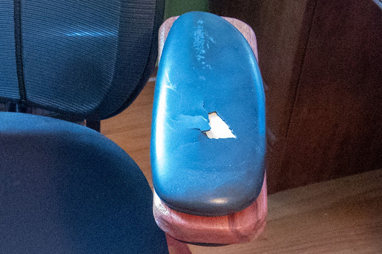
The only problem was that its armrests (made out of some artificial leather) started to wear down.
So I substituted original armrests with DIY wooden.
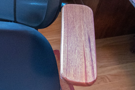
I can tell you that after modification chair becomes even better. For comparison I made a photo of the old, worn out armrest.


