Saturday, December 18, 2021

With the Help of a Soda Can Tab


I have several precision screwdrivers. They are from different vendors  and have different length. All of them are of decent quality and deserve some good care. For screwdriver to be in service for a long time it is important  to use them with proper match: right screwdriver for the right screw.  To make selection of screwdriver easy I made myself the screwdriver stand.


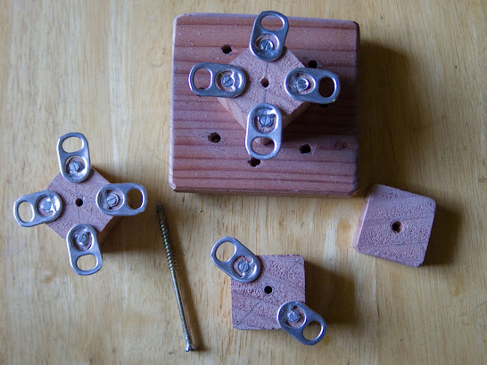
On the picture above there is elements from which I made the stand:
  • Several wooden pieces (made out of redwood)
  • Ten soda can pull  tabs.
  • Long screw for wood.
And here is the stand.


Now I can easy select whatever screwdriver I need. 

I have found that soda can tab to be an valuable item  in my hardware inventory. I even created instructable    with description of its various usage . Will free to borrow whatever you find suitable for your needs.


Wednesday, October 20, 2021

Where does Sound Come From

 Clip below make a sense to watch only if your computer (or other internet device) is NOT mute.


I have three audio devices connected to my Windows  10 desktop:
  1. Headphone as part of headset (Mpow 323 model) plugged into USB.
  2. Stereo pair of standalone external speakers plugged into  3.5 socket.
  3. Speakers integrated into Philips Monitor (HDMI).
I often need to switch between speakers and headset (seldom use Philips speaker).  Obviously it could be done by Windows dedicated sound menu, but I feel that its usage is not convenient. I want two things:
  • Ability to switch between sound output devices just by mouse click. 
  • Ability to hear proper audio feedback to be sure that selected device is up and and running.
After some investigation I have achieved the desired outcome with the help of two utilities which I   took here: https://www.nirsoft.net/  Software is documented well enough with chm help files.  (I am not affiliated with the owner of that site, just happy user of his software. Software is free). 
First utility is executable "SoundVolumeView.exe". It is a GUI which allows to explore  available sound devices and controls them (enable, disabler, set default etc...).


On the screenshot above you can see selected devices, which are subjects of this project. Right click of the mouse while on selected device invokes context menu. On that menu you can choose "Property" element and see  pop-up window.  This window among other information has the field "Command-Line Friendly ID". 

This is good: in addition to explore devices and control them with GUI I can achieve desired outcome by the command line or batch file. 

So to set headset as default output device one invokes next command:
 C:\NirSoft\SoundVolumeView.exe /SetDefault "Mpow 323\Device\Speaker\Render" 1

But that solves only first item in my list. What about audio feedback. Here I use another utility within the same package: "nircmd.exe". Among many commands it has command "speak". Command line to invoke it I use in this form:

C:\NirSoft\nircmd.exe speak file  "C:\NirSoft\headphone.xml"

And here is a context of "headphone.xml" file:

<voice required="Gender=Male">
	Headphone Activated
</voice>

As you can see it has only one xml attribute <voice> which control gender of the speaker and text to speak.

Similar files created for other two devices.   Here is "speakers.xml":

<voice required="Gender=Female">
	Speakers Activated
</voice>

It took me some time to find out the third distinctive voice. Eventually I have settled with attribute <lang> with decimal code. The result was funny voice with some specific accent. So here is "philips.xml" file. 

<lang langid="419">
   Philips Activated
</lang>

After that I made three batch files:

"headphone.bat"
C:\NirSoft\SoundVolumeView.exe /SetDefault "Mpow 323\Device\Speaker\Render" 1
C:\NirSoft\nircmd.exe speak file  "C:\NirSoft\headphone.xml"

"speaker.bat"
C:\NirSoft\SoundVolumeView.exe /SetDefault "Realtek High Definition Audio\Device\Speakers\Render" 1
C:\NirSoft\nircmd.exe speak file "C:\NirSoft\speakers.xml"

"philips.bat"
C:\NirSoft\SoundVolumeView.exe /SetDefault "NVIDIA High Definition Audio\Device\PHL 252B9\Render" 1
C:\NirSoft\nircmd.exe speak file "C:\NirSoft\philips.xml"


The last step was to create three desktop shortcuts. I put here just one as example. Shortcut  doesn't invoke batch file directly. Instead it calls batch file with the help of "nircmd.exe". You see that it is called with  command "exec", parameter "hide", and name of the batch file. Parameter "hide" guarantees that console window attached to the command line  process becomes hidden and does not distract the user.


Thursday, September 30, 2021

Ballpark


I am studying baseball. No, I am not trying to play baseball. I just would like to understand it.
This September I was in Oracle Park to watch the game between host San Francisco Giants and visiting team Atlanta Braves, Here are photos of Giants starting pitcher Anthony DeSclafani at various stages of the pitch.


And here is how it looked  at the other end of the pitch. Giants catcher is Buster Posey. Which player at bat from Braves team are am not sure.


Both team needed the win to stay on the top of division. Giants looked like in better position: they had best record in MLB and secured playoff at least as wild card player. Braves was under pressure of coming very close Phillies and without a chance to get a wild card place in case Phillies will be at first. But that particular day was not good for Giants. They lost 0:3. And now thirteen days later  at the end of September, position of Braves looks better compare to Giants. Braves clinched the division, while Giants is still fighting vs Dodgers to be on the first place. 
While game result was a disappointment, I became the witness of the seldom baseball event: Braves hitter Eddie Rosario hit for the cycle: single, double, triple and home run. If you  need to know what does that mean you better to consult some credible source: I myself got the knowledge about that event just when it happened. What I do know now that within ~150  years of MLB history such an event took a place only 304 times, in other words in average two times per year. To understand specialty of this event take in to account that 2430 games are played in the regular MLB season not counting the postseason.  Guess how many photos of Eddie Rosario I made during that game? No single photos, nil. Next time I will try to picture each hitter at least once. Just in case something similar occurs.

To know more about that particular game you can visit this link:


And here is just one more photo from the park. It is nice place to be especially when there is sunny September day.


Update 10/03/21. Giants won the division at the last day of the season, They beat Padres and gained 107 wins (franchise record). They will play playoff series against winner of wild card game: Dodgers (Los Angeles) or Cardinals (Sent Luis).
 
Update 10/14/21. Today Giants lost series to Dodgers while Braves still alive and will play Dodgers in National League series. In Bay Area baseball season is officially over.
  
Update 10/17/21. Yesterday Braves played first game of the series  against Dodgers. And both heroes of the game against Giants showed remarkable performance.  Eddie Rosario scored for Braves very first run. In the first inning he singled, then stole second base, then reached third on groundout and eventually reached the home on the wild pitch. Overall Braves scored three times, while there pitcher Max Fried allowed only two runs. It make a sense here to put picture of Max Fried taken on September 19 game against Giants.


Update 11/04/21.  Two days ago Braves won world series. The last winning game against Astro they finished with score seven to nothing. Guess who was the starting pitcher for the Braves? Right, Max Fried.


Friday, September 17, 2021

Hare


I made photo of this hare (or jackrabbit -  not sure how to properly name this creature)  this September in proximity of town Williams, California. Seems like it completely ignored presence of people around.  So we came to it very close. Some excerpts of photo EXIF:

  • Camera model: Pentax KP
  • Lens: Pentax SMC DA 18-135mm
  • Exposure time: 1/60 s
  • Aperture f-stop: f8
  • Focal length: 135mm
  • ISO 200
  • Capture Time: 9/13/2021 8:15 AM.
Eventually, when we came too close, hare raised and start to run. I tried to picture it running. That attempt was not absolutely successful and photo came out far from perfect. Still I decided to put it here just for the sake of comparison.


Run, Jackrabbit, run!


Sunday, August 8, 2021

Speed Bag


Here is the speed bag which recently  I have added to my home gym. Speed Bag and swivel I bought online.  The rest of components came from the local Home Depot. I attached the construction to the beam, which holds the roof of our patio.


Obviously construction looks primitive and skilled boxer unlikely will approve it. But my goal is just to keep my elbows and shoulders in agile state while having some fun in the process.  This project  serves me well for that.


Sunday, July 18, 2021

Camera Handle


On the photo above you can see small digital camera with attached handle. I believe such a handle  provides comfortable and steady grip. As a foundation of that  handle  this L-Plate used . It is not of highest  quality but is inexpensive and suites this project well. I unscrewed short side of the plate and made out of 1/4 inch plywood and metal corner four elements of the handle. One more element (aka half-cylinder) I made out of broken hammer handle.


Handle assembled as a sandwich with plywood sides and metal inserts. During assembling I applied universal glue first than fixed it with metal screw.  Then I glued half-cylinder with wooden glue and   I painted it with some dark stain. The goal was for it look old and vintage rather than new and shiny.


Assembled handle is screwed to the plate in place of its short side.


While intension was to use it for smaller mirrorless camera I have tried it with bigger DSLR and it works OK here as well.


Sunday, July 4, 2021

Two against One


Clip above shows Attiny85 chip controlling two 10mm LEDs with the single pin. This post discusses schematic and programming of such a solution.

There are two ways to control LEDs with microcontrollers (like Attiny85).
One way would be to connect LED cathode to the chip pin and LED anode through the current limiting resistor to the power supply '+'.  To light up the LED you just need to program pin low. To turn it off  you need to program it high.

Another way would be to connect LED cathode to the ground and LED anode through the current limiting resistor to the  chip pin. To light up the LED you need to program pin high and low otherwise.
Which way to prefer? I can't tell. I myself often choose it based on how well it corresponds to controls of other devices in particular project.

But there are not that many pins on the chip like Attiny85. What if number of pin available is less than number of LEDs needed to be controlled.
On the circuit diagram above you see the method  of controlling two LEDs with single pin. It based on three important facts:
  1. Any LED has some forward voltage. For Green/White 10mm used here it exceeds 3 V.
  2. Microcontrollers pins may be programmed not only to provide output signal but to collect input as well, If pin is programmed for input it presents itself for external components as a circuit with very high resistance.
  3. Human eye can't see light blinking if its frequency exceeds 50 Hz. If circuit switches LED off/on fast enough (more than 50 times per seconds) you will see it as always lighted.
Rules to controller LEDs here are next:
  • If pin set high green LED is dark and white LED is lighted.
  • If pin set low green LED is lighted and white LED is dark.
  • If pin set into input mode both LEDs supposed to be dark, because sum of forward voltages on both LEDs exceeds power supply voltage,
I assembled the circuit and programmed it , but result was  disappointing. Setting pin into input mode did not turn both LEDs off, They were lighted up. The light was  less bright than normally but still visible.  Would resistors increase help? Alas not that much. LEDs dimmed a little but not fully. Obviously I need either decrease power voltage or look for LEDs with bigger forward voltage,
Then idea came to mine mind: what if I add to the circuit extra devices with some forward voltage.
Here you see each LED sequentially connected to  the silicon diode . Forward voltage of diode reaches 1 V,  which makes whole forward voltage of both (LED and silicone diode) ~ 4 V.  Obviously it is better to decrease value of resistor to keep current the same  (~20 mA). And this circuit solved the problem.  I believe it is not bad solution taking in to consideration that silicon diode cost pennies, Below you can see C program to run the test. 

#include <avr/io.h>
#define 	F_CPU   1000000UL
#include <util/delay.h>

typedef enum {OUT_LOW, OUT_HIGH} OutputLevel;

#define pinOut(bit, outLevel) \
(DDRB |= (1 << ( DDB##bit)));\
switch(outLevel) \
{\
	case OUT_LOW: (PORTB &= ~(1 << (DDB##bit))); break;\
	case OUT_HIGH: (PORTB |= (1 << (DDB##bit))); break;\
}

#define pinIn(bit) \
((DDRB &= ~(1 << (DDB##bit))),\
(PORTB &= ~(1 << (PORTB##bit))),\
(PINB & (1 << (PORTB##bit))))

int main(void)
{
    while (1) 
    {
		for (int i=0; i < 100; i++) { // White & Green
			pinOut(2,OUT_HIGH);
			_delay_ms(5.0);
			pinOut(2,OUT_LOW);
			_delay_ms(5.0);
		}
		for (int i=0; i < 100; i++) { // White
			pinOut(2,OUT_HIGH);
			_delay_ms(5.0);
			pinIn(2);
			_delay_ms(5.0);
		}
		for (int i=0; i < 100; i++) { // Green
			pinOut(2,OUT_LOW);
			_delay_ms(5.0);
			pinIn(2);
			_delay_ms(5.0);
		}
		for (int i=0; i < 100; i++) { // No light
			pinIn(2);
			_delay_ms(10.0);
		}
    }
}

But one may ask why this? Why not charlieplexing?  Indeed charlieplexing is well known technique which utilizes facts of of pin high resistance while  in input mode, and non-ability of human eye to see  high frequency light oscillation. It can provide LEDs/pin ratio not only 2 but much bigger. To compare  let us look at charlieplexing example with the same LED/pin  ratio: 2. There is need to have three pins to control six LEDs.  But how to control just four LEDs, or two? Not possible. And in addition you need to connect/solder five components to the single dot which for DYI project presents some challenge. 


So in a conclusion: even if charlieplexing is great there could be  cases when method described in this post is a valuable solution.

Update 07/05/2021. I put link to this post on the AVR subreddit . And I got some comments that there actually different schematic exists which allows to control two LEDs with the single pin without need of silicon diodes.

Indeed such circuit works perfectly. But again nothing is free. It consumes ~ 20 mA even if both LEDs are off. Meanwhile for circuit  with silicon diodes consumption during dark time is much smaller. So which circuit to choose is really question of use case and preferences.

Wednesday, June 2, 2021

Looking Back


Recently I became a proud owner of 2008 Ford Ranger (regular cab, 7 feet bed, v6 4.0 engine, automatic). The car obviously seen a lot.  Could I  prolong his life for a while? For the beginning I decided to equip it with back-up camera. On e-bay I bought Type-S solar powered kit. Kit consists of two parts:
  •  License plate frame integrating back-up wireless camera, solar panels,  and battery.
  • LCD monitor.

Installation of the camera was easy: first I charged its battery via phone USB charger and then installed it in a regular way in place of license plate frame. Further charge supposed to be provided by sun light.

But installing the monitor required some job. Kit had the  holder with suction cup, but that was a jock. It could not hold monitor for more than five minutes. So I needed to invent some other way.


As you can see there is some opening beneath climate control panel. Could it get some use? 


On the photo above on the left you can see supplied holder and on the right some metal part which I found at the local Ace hardware store. I have no idea for what it was made for but its size more or less matched the opening  under dashboard. I cut it a little and treat with file to make it fit.


Form the holder I removed suction cup, cut the plywood rectangle, drill in hole  under the angle ~60 degree and inserted handle rod through it. On the picture above you can see rear view of assembled construction. On the picture below  there is the side view.


Then I just pushed it into the opening under climate control panel. Metal shape is rigid enough to keep construction in place. Size of the  monitor is a good match to car dashboard. As soon as I inserted power cord into the car 12 V socket, monitor turned on and paired with camera. Done.

What can I say about the kit? So far I like it. Ability to install camera without messing up with car electrical wires is a plus. How well solar charger will work and how long battery will keep the ability to get charge? Only time will tell. Monitor screen itself is good: right size and good enough image quality. There are one small problem: Ford Ranger power socket does not turn off when ignition key is taken out. According to camera manual I should not keep monitor powered up while not driving to avoid car battery discharge. I believe that discharge should be minimal but as of now to play it safe I will remove power plug when car is parked.


Thursday, April 1, 2021

1/4 Sized Breadboard


In the photo above there is Adafruit small breadboard. I found it to be a perfect match for projects utilizing Attiny85 microcontroller. 


While it is single side board, top side has copper circles around holes so components can be soldered on any side of the board. Board is not very thin and feels sturdy. Occasional soldering overheating will not damage conductor strips. Conveniently it has four strips for power and it is well suited for projects needed two voltage levels (like 5V and 12V).

So far I used such a board for two projects  made for last year Halloween  (published here). 


First project is to control two three colors LEDs. It is minimalistic: apart of controller board accommodates just three resistors. To make controller programmable in-board there is  6 pins ISP male header. I soldered pins, cut strips between two pin rows with the knife (cut is on the bottom side of the board) and wired them to corresponding pins of the the microchip.


Second project required two voltage levels (12V and 5V).  See 12V-5V stepdown power supply on the right side of the board soldered to it. There is no 6-pins ISP header on the board, Does that mean there is no way for in-board programming? Absolutely not. To make microchip in-board programable I mounted on each side of the chip female headers. Because of that board becomes suitable for AVR ISP to Attiny85 adapter  and  can  be   programmed the same as projects mounted on non-soldering breadboard.


Saturday, March 6, 2021

Capabilities of Supercapacitor


Several years ago I built the project utilizing supercapacitor (useless machine). Now I returned to this component again to make a set of small projects, which  will use super capacitor as backup power supply. Clip above shows initial test. Several seconds of charge is enough to power Attiny85 chip controlling blinking be-color LED for five minutes. At the end of this time LED blinks are barely visible but anyway I found result impressive. In case you need details, here is circuit diagram:


 And here is list of components:

  • Supercapacitor 0.1 F, 5.5 V (NEC)
  • Attiny85 microchip
  • Red-Green bi-color LED (5mm)
  • Resistor 180 Ohm, 0.125 W
  • Diode Schottky ( 1N5817) (for this test it is not really needed but later I will utilize it to detect the moment  when external power is down).
Circuit initially powered up by 5V USB 0.5 A power supply.
 Code is short, so I put it here as well.

#include <avr/io.h>
#define 	F_CPU   1000000UL
#include <util/delay.h>

typedef enum {OUT_LOW, OUT_HIGH} OutputLevel;

#define pinOut(bit, outLevel) \
(DDRB |= (1 << ( DDB##bit)));\
switch(outLevel) \
{\
	case OUT_LOW: (PORTB &= ~(1 << (DDB##bit))); break;\
	case OUT_HIGH: (PORTB |= (1 << (DDB##bit))); break;\
}

int main(void)
{
    while (1) 
    {
		pinOut(0,OUT_LOW);
		pinOut(2,OUT_HIGH);
		_delay_ms(200.0);
		pinOut(0,OUT_HIGH);
		pinOut(2,OUT_HIGH);
		_delay_ms(800.0);
		pinOut(0,OUT_HIGH);
		pinOut(2,OUT_LOW);
		_delay_ms(200.0);
		pinOut(0,OUT_HIGH);
		pinOut(2,OUT_HIGH);
		_delay_ms(800.0);
    }
}

Sunday, February 28, 2021

AVRISP II adapter to Attiny85


For my hobby projects  I often use Attiny85 chip . Usually first stage of the project is breadboard prototyping. But there is the problem: connecting AVRISP programmer to the chip on the breadboard is not that easy. So I made dedicated  adapter  which allows effortless connection between  AVRISP programmer and Attinny85 chip. 

\


Adapter is passive: it contains nothing but headers to connect programmer and headers to connect to the chip. Apart of that added LED with resistor to indicate if power is supplied.


Adapter has two set of headers:

  •  one set to connect AVRISP (on the photo on the left)
  • another set to insert into breadboard on top of Attiny85 chip.
LED with resistor added for convince to be sure that power provided to the circuit. Marking on the circuit diagram below corresponds to the photo above.
Here you can see the breadboard with the microchip attached to the power.


I need just put adapter with connected AVRISP II programmer on top of microchip, connect AVRISP programmer to a computer through USB in interface, and start Atmel Studio.  Now I am ready to program.


One may ask why not to buy some breadboard ready ISP header? Indeed for less than one dollar you can get adapter kit at  Adafruit site. It is nicely made and can be used with any AVR device. But to make it work there is need to connect that adapter to a controller with six jumper wires. With my adapter I just need to snap it in place. Obviously, if I want to work with different controller (like  Atmega328), I have to make another dedicated adapter. Still I assume that benefits worth the effort.


Saturday, February 13, 2021

Chessboard Chair


We have a small folded chair with top made out of sawdust wood covered with  plastic . We left it in backyard for some time and it got under the rain. As a result top edges started  to decay with  plastic  partially detached. But surprisingly painted metal frame was intact. I decided to renovate the chair by changing the top. While looking for proper board I have found in our home wooden chess board which did not get much use lately. So unscrewed old top and mounted chessboard instead.  Old chair legs tips (couple of them lost) I replaced with  3/4" chair tips I bought in the local Home Depot. On the photo above you can see the result.

And here is old top. I still keep it. Maybe I can restore it and it will find another usage.